About Precise Straightener.
Time:2021-02-03
Views:2763

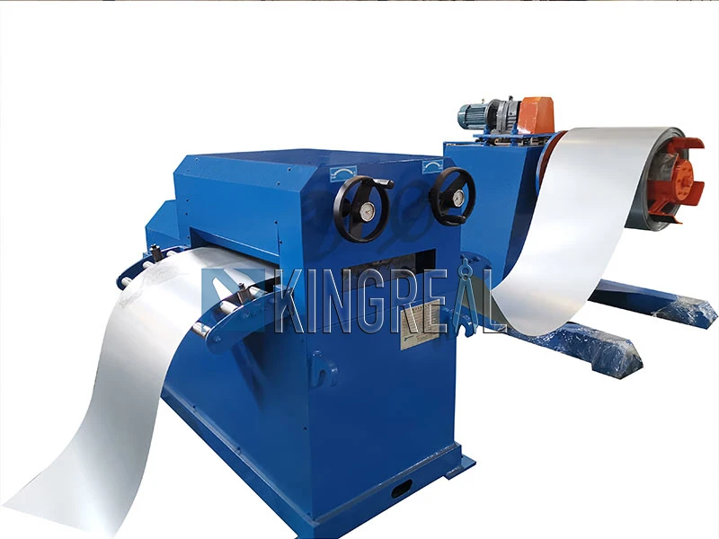
The main executive components of the entire system are the upper and lower rows of rollers. The front and rear roll gaps of the upper and lower rows of rollers must be adjustable, and the row of rollers themselves must be rotated, so that the entire system is divided into a position control system and a feeding speed control system. Due to the plastic deformation of the plate to be leveled, the actuator is required to maintain good rigidity under strong load, and the servo control system can achieve high control accuracy, so hydraulic servo control is used to achieve this. The position control adopts a valve-controlled hydraulic cylinder structure, and the flow rate is adjusted by a proportional servo valve to realize the position change of the hydraulic cylinder; the speed control adopts a valve-controlled hydraulic motor structure, and the flow rate is adjusted by a proportional valve to realize the speed change. Since position and speed need to be coordinated, both the position control system and the speed control system are centrally controlled by PLC.
In the position control system, the power source is two hydraulic pumps with different flow rates driven by the same motor, the actuator is a hydraulic cylinder, and one hydraulic cylinder is installed at each of the four corners. Considering three points, a plane is determined, and the front row is left and right. Each hydraulic cylinder is controlled by its own proportional servo valve, and the left and right hydraulic cylinders in the rear row are controlled by the same proportional servo valve. The flow change of the hydraulic cylinder determines the up and down movement of its position. The displacement sensor next to each hydraulic cylinder detects the current position of the hydraulic cylinder. The position quantity is input to the PLC through the A/D module, and the corresponding control quantity is obtained by adopting an appropriate control strategy and output to the D/A module. The output analog quantity is amplified After that, the flow rate change of the control servo valve controls the up and down movement of the hydraulic cylinder.
In the feeding speed control system, a pump motor type volume throttling speed control loop is adopted. The pump drives the hydraulic motor and drives the upper and lower rows of rollers respectively through the transmission. Because the speed control accuracy is not high, a proportional valve is selected to adjust the pressure oil flow input to the hydraulic motor, and then control the speed of the upper and lower rollers. Optical encoders are installed on the central shafts of the two hydraulic motors, which rotate at the same speed as the motors, and output pulse signals to the PLC‘s high-speed counting input. The high-speed counter calculates the upper and lower roller speeds and displays them on the touch screen interface in real time. If the rotation speed of the upper and lower rollers exceeds 10%, the panel indicator will alarm. At this time, you can manually fine-tune the throttle valve opening at the input end of the hydraulic motor to adjust the speed of the upper and lower rollers to make the upper and lower rollers basically consistent.


