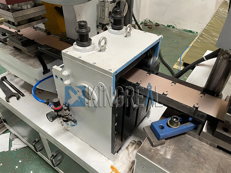
Working Principle of NC Servo Feeder
Time:2021-02-21
Views:2735

Compared with the roller feeder and the air feeder, the NC feeder has higher feeding accuracy, more stable feeding performance, and more convenient operation. These advantages are derived from its advanced control system. The control system of the NC feeder is composed of (Mitsubishi) PLC, (Yaskawa) servo system and (Wilun) touch screen. PLC can improve the stability of the control system and enhance the anti-interference ability of the system; the servo system can accurately locate the mechanical movement position, Improve the accuracy of mechanical transmission; the touch screen can visually display and modify the parameters of the NC feeder, simplifying the on-site operation.
PLC is the core component of the NC feeder. Jinzhide NC feeder is equipped with Mitsubishi PLC as standard. It has a built-in high-speed pulse output function that can directly send a quantitative pulse number to control the operation of the servo drive. The servo driver controls the rotation position and speed of the servo motor according to the number and channel of pulses sent from the PLC pulse output terminal, so as to accurately give the feeding length. The touch screen can visually display various parameters of the personalized system, provide users with a good human-computer interaction interface, and simplify on-site operations.
The NC feeder has two working modes: manual and automatic. In manual mode, the servo motor can rotate forward or backward, and when it is automatic, the servo motor can only rotate forward.
When in manual working mode, at the rising edge of the servo forward signal, execute ACC (frequency acceleration/deceleration control) command, set mode control data, realize CW (clockwise) rotation, and make the servo motor rotate forward. At the falling edge of the servo forward signal, execute the INI (action mode control) command to stop the pulse output. The servo motor reverse situation can be analogized.
When in the automatic working mode, the PLC sends the preset pulse to the servo drive device, at this time the PLS2 (positioning) instruction is executed.
Description of several key parts in the PLC program of the NC feeder:
1. The PLC program converts the set length on the touch screen into the number of pulses
PLC calculates the number of pulses sent to the servo drive according to the set length. The number of pulses per set length can be expressed by the following formula:
Pulse number=(set length×standard pulse number)/(electronic gear tooth number×standard length)
Note: The standard length is set to 1m, and the standard pulse number refers to the number of pulses needed to send 1m material.
PLC output uses floating point arithmetic, and input parameters must use floating point format. The pulse setting in the high-speed pulse output instruction must be a BIN number, so afterwards, through FIXL, the instruction converts the calculated pulse number into a B1N number format. The number of electronic gears of the servo drive is set to 5.
2, the actual length of pulse number revolution
In order for the operator to better grasp the working conditions of the feeder, it is very necessary to display the feed length in real time. The method is to read the actual pulse number of the PLC, convert it to the actual length value by the all-rounder, and display it on the touch screen. The actual length of pulse number revolution can be expressed by the following formula:
Actual length = actual pulse number × electronic gear tooth number × (standard length/standard pulse number)
3, feeding speed to pulse frequency
For workpieces of different lengths, the feeding speed requirements are different; longer workpieces need higher feeding speeds, otherwise it will conflict with other equipment; for shorter workpieces, lower feeding speeds can be selected to protect the motor. Therefore, it is necessary to read the high speed multiplied by the set percentage from the touch screen to be the feeder speed, and then convert it into pulse frequency.
4, pulse frequency transfer speed
While the feeding length is displayed on the touch screen in real time, it is also necessary to display the feeding speed. The method is to read the pulse frequency sent by the PLC and divide it by the high speed to obtain the display percentage.


